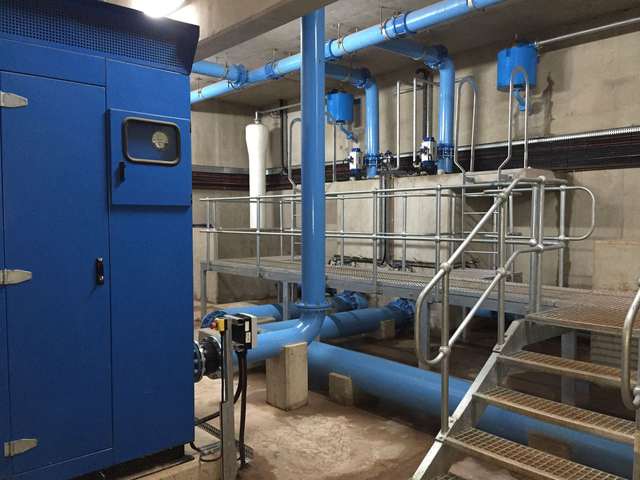
Design-and-build potable water treatment facilities and plant upgrades.
Specialist design for new, retrofit and rehabilitation works.
Instrumentation and control systems for reliable, monitored operation.
Long-term operational support for sustained plant performance.
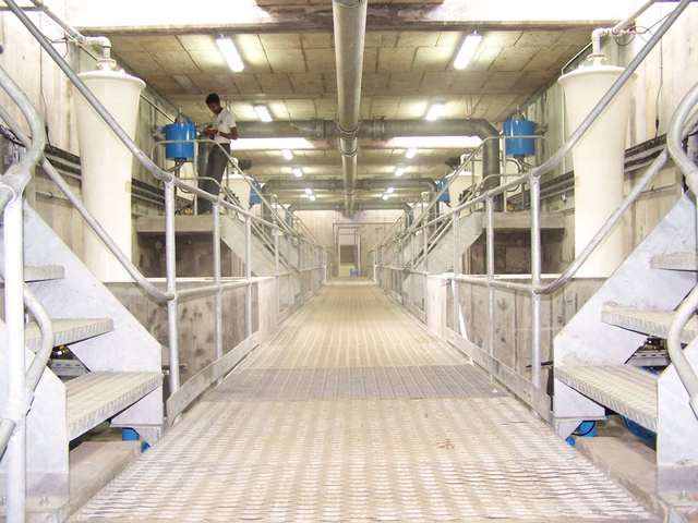
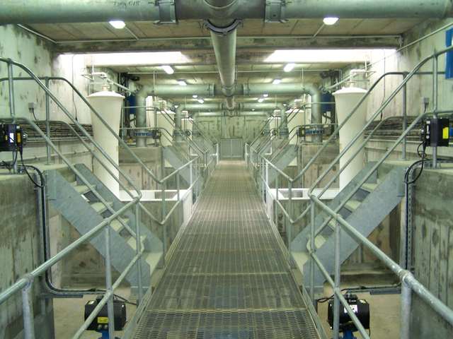
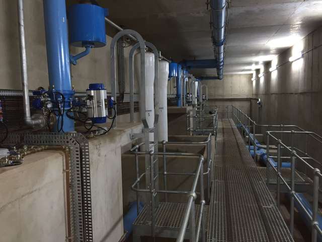
A filtering battery may comprise filters that have to be supplied as evenly as possible, especially avoiding any over-feed to one of the filters. Special attention must be paid to this problem when the battery only has two or three filters.
Gravity filters have three main hydraulic operating modes:

These are constant output and variable level filters.
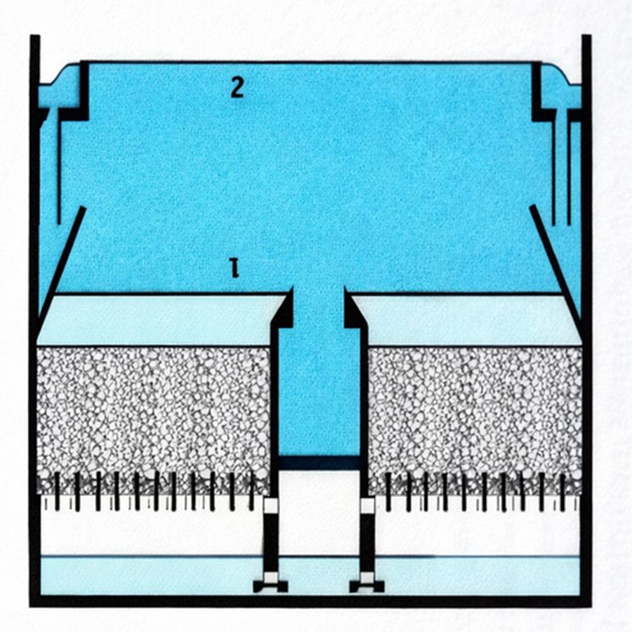
The entire throughput to be filtered is evenly distributed at the filter inlet, where water falls from a variable height depending on the level of fouling.
When the filter is clean, the water level (1) is set by the level of the filtered water outlet weir. At maximum fouling, the level rises to the supply water level (level 2).
In general, this water level rises from 1.50 to 2 m, depending on filtering mass granulometry.
These filters tend to be more basic, but there is a danger that the floc will break up, possibly affecting filtered water quality.
At the same time, the aim is to ensure that the water level over the filters remains fixed or only fluctuates slightly, and that the filtered water delivered 2 to 3 metres lower maintains a flow rate that is constant and equal to the total incoming flow rate, divided by the number of filters.
A filter rate controller mounted on each filter’s outlet maintains a constant flow rate, regardless of the filter’s level controller. The system includes an equal distribution mechanism. This device generates a secondary head loss that becomes significant when the filter is clean and which is cancelled out when the filter is completely fouled. In this way, the filter rate controller compensates for filter bed fouling.
Compared with constant rate variable head filters, constant rate compensated-clogging filters have the advantage of stable treated water quality and reliable operation, even in cases involving sudden flow rate fluctuations.
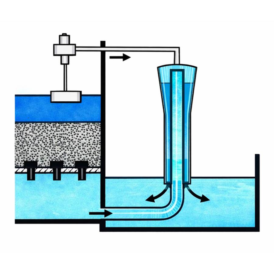
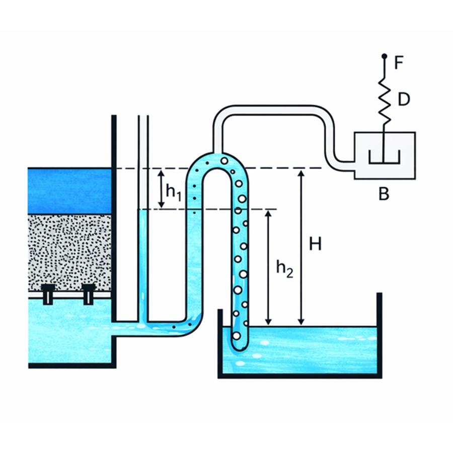
This system is used to maintain a constant level in the filter by utilising the siphon to determine the level and the partialisation to control the vacuum through the siphon (hydraulic system).
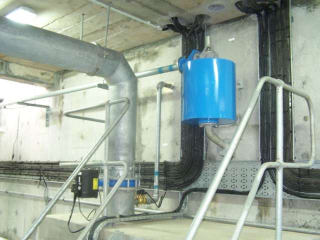
The AQUAZUR® Concentric Siphon and its Partialisation Unit are used for level control. The partialisation unit constitutes a measuring and control unit, and the siphon is a control unit.
This unit consists of two concentric tubes. Flow goes from the inner branch to the outer branch.
When air is injected into the top, it is drawn by the water into the downstream branch where the air-water mixture density is lowered, reducing the vacuum in the neck.
Without partialisation air, the vacuum at the neck is equal, within the pressure drop in the downstream branch, to the height “H”, which is the difference between the filtered water level and the downstream filtered water chamber level.
With air partialisation, this void is reduced to height “h1”, equal to the product of “H” by the water/air mix density. The difference H – h1 = h2 represents the pressure drop thus created by the air input.
If h1 represents the pressure drop, with a clean filter, caused by the passage of the flow to be filtered through the filtering bed, the floor and the filtered water outlet pipe to the siphon neck, h2 represents the fouling depth available for the filtering bed.
All we need to do is, with a clean filter, inject enough air to create a pressure drop h2 and, as the filtering bed becomes fouled up, reduce the air flow down to zero so that h1 increases up to H.
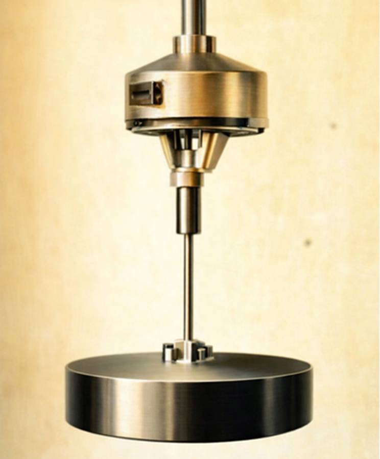
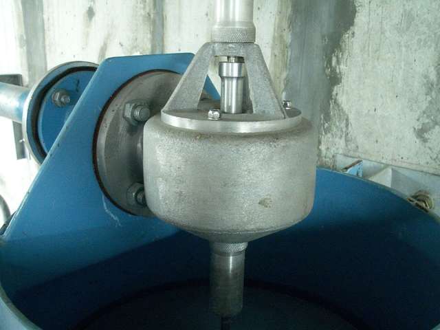
This is the control mechanism used to inject air into the top of the siphon to control its flow rate.
The air flows through an opening. The section of this opening is altered by a moving component comprising a float and a return spring.